[0:00]So hello everyone, welcome back to the another lecture. So my name is Ashish and today we will start with the first lecture of this dual active bridge playlist. So it is an introduction and core concept of DAB lecture. So what topic we are going to cover in this lecture is we will talk about what is DAB converter. Then power flow basics, like how the power is going to be flow from one bridge to another bridge and what is the core concept. Then derivation of power flow fundamental like we will take one a particular example, like how the power is flow from one part to another part. And from that particular concept, we will form the principle of operation of the DAB converter. So we will understand, okay, because of this basically the power is going to flow from one part to another part, okay.
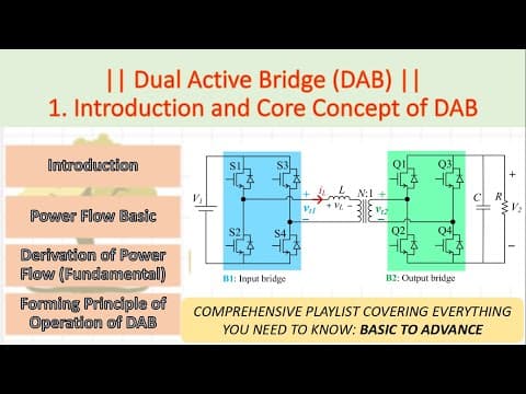
[0:51]So all these things we are going to cover. So what is the important thing you should understand about the DAB? First thing you should keep in your mind is that in DAB converter, the DAB converter is we will mostly use for high power application, okay. And what is the motto here, we need to transfer the power from one bridge to another bridge, okay. So power transfer is our ultimate motto to use the DAB converter for a medium to high power application, okay. Now we will start with this particular video. So we are here on one particular screen. Now we will start with very basics. So this is the DAB converter which you already know, right? So we have basically a DC voltage source at this particular point and there is a one basically bridge, which is I will assuming here it as a input bridge and then there is a very high frequency transformer is there. And then another basically output bridge is there and then I have my load. So either it may be a load or it is another kind of source. Just like the voltage V1, it might be a V2. So what is DAB? So DAB is a isolated DC to DC converter. Why? Because the high frequency transformer is there. It is a bidirectional, power can flow from B1 to B2 and also from B2 to B1. So it is a bidirectional converter. So that is why I told you that this particular resistance are can be V2 as well, okay? So this can be as a source as well. So either the power will flow from this particular bridge to this particular bridge, or from this particular bridge to this particular bridge, okay? So the power can be flow in bidirectional. So this is the first point we understood. Now we need to understand how the power will flow from one bridge to another bridge or from another bridge to the first bridge. So this thing we are going to understand. Now this DAB converter is there, so you can see that once the bridge's done, so at this particular point, some voltage will be induced. On the same hand, if the voltage is induced at the primary side, this basically its corresponding voltage will be induced in the secondary side, right? So some voltage will be induced in this particular point and some voltage will be induced in this particular point, V as of now don't know what is the nature of the voltage which is going to be induced. So we mark it as a VT1 and VT2. But we don't know that what is the nature of this particular voltages, right? But we will, we can derive this, but as of now we are not interested, what is the nature of the voltage will come at this particular point? We wanted to know if this particular some voltages are there, what we need to do next, okay? So some voltages will come here, okay? So just keep this particular point in your mind. Now let us start our discussion. So let us assume one particular circuit where my two AC voltage sources are there, one at V1(t), another as V2(t) and the current flowing through this IL and some L inductance is there of the line. So it is a kind of the short transmission line, you know that primary side voltage is there, secondary side voltage is there and L is a inductance of the transfer type, that is a XL, okay? So and current is flowing through this. Now, how the power is flow from one particular side to another particular side? So this thing we should understand first. So let us mark the voltages V1 as V1 at an angle of 0. So I'm assuming here is that my V1(t) is a reference voltage. So reference voltage and that's why I keep it as angle of 0. And my V2, I am keeping it as a V2 at an angle of minus of del, okay? V2 I am keeping here as V2 at an angle of minus of del. So you learned this concept that in transmission line or basically how the power is flow, the power is always flow from higher load, higher angle to lower angle. So this is angle 0 and this is angle minus of del. So how the power is going to be flow? So power is going to be flow from this particular V1 to V2. As both are sources, but still power is flowing from V1 to V2. Now we power, if I wanted to flow the power from V2 to V1, what should we happen? This particular V1 should not be at the reference and angle of the V2 should be greater than angle of the V1. If this is the case, then power will flow from V2 to V1, okay? So this basic thing we understood. Now what is my L? So X is basically omega L I am keeping. Now can I know the what is the current flowing through this particular path? Yes, so I know IL is equal to the V1 and V1(t) - V2(t) divided by XL. And we already defined what is V1(t) and V2(t). So I have just keep this particular value. Now V2 at an angle of minus del, what I can write it down? V2 e raised to the power minus of J del. So this is a very basic fundamental expression. Now V2 e raised to the power minus of J del, minus of del, if I wanted to break it through the real and imaginary part, how I can write it down? V2 e raised to the power minus of J del as V2 cos of del - J sin of del. So this is a very fundamental identity. Now so overall numerator term, what I can write it down, that is V1 - V2 e raised to the power minus of J del, how I can write it down? So I have just clubbed the real terms one side + J imaginary term another side. So overall what is my IL is coming here? So IL is overall whatever the expression I got here, I have just keep it here divided by JX, okay? So this is the thing. Now another thing is basically, I have just this is 1/J, so 1/J is nothing but the -J. So just I have basically separated the real part and some imaginary part here. So what overall expression of IL I am getting? V2 into sin del divided by X - J V1 - V2 into cos del divided by X. So I got what is the current will flow through this particular branch. Now I have IL, okay, so can I get what is the real component of IL and what is the imaginary component of IL? Yes, so the term which is excluded from the J is my real component and the term which includes the J, this is my imaginary component. So I got what is the I real and I imaginary, okay?
[7:16]So I know that okay, if such a short of system is there, then I first thing we understood that the power is control, power will be flow from higher angle to lower angle. Then we have calculated that what is the current flow and what is the real part of the current which is going to be flow and what is the imaginary part of the current which is going to be flow. Now the complex power delivered by V1. So we know that power will flow from V1 to V2. So how the complex power delivered by the V1, what is the formula? S1 as a V1 at an angle of 0 into IL conjugate. We know VI conjugate is the basic formula for complex power. Now substituting the value V1 and what is the value of the IL conjugate? I have just keep it here. And what we get, I have just tried to separate out the real part and imaginary part. So therefore, so what is total complex power? It is the addition of, like it is the active power + J times of reactive power, right? So I have just tried to separate them out and what is the real part? V1 V2 divided by X into the sine of del + J times of something. So this part corresponding to the reactive power and this part corresponding to the active power. So that is why from this particular expression, I got the active power formula, that is a P1 equal to V1 V2 by X into the sine of del. So this is the my active power formula. So the same thing what we have learned that active power flow from higher angle side to lower angle side. And if such a sort of system is there, what is the overall formula for the P? That is a V1 V2 by X into the sine of del. And who will decide the power will flow from V1 or V2? So it is decided by this particular angle del. So if this particular angle del is positive, which is the angle between the V1 and V2. If this particular angle del is positive, power will flow from V1 to V2. If this angle del is negative, power will flow from V2 to V1.
[9:19]So I hope so till this particular point we have understood that how power is flowing, okay? Now can this same concept we can extend to the DAB converter? That we will going to see. So this is the my DAB converter. Now just try to relate this particular figure here. So this is the DAB converter. So how exactly the DAB converter is? So we have some voltage here, okay, then we have the bridge one, then my have inductance here, then I have my basically high frequency transformer, then I have another bridge here and then my another voltage V2 is here. Another voltage V2, which is either basically a kind of the load as a resistive load or it can be a battery, okay? But V2 is there. So if it is not basically, if it is a resistive load, so by default we know that power will flow from V1 to V2 only because this will not going to basically deliver the power, okay? It will only consume the power, but if it is a basically battery or some sort of another active source, then power can be flow in backward direction as well from V1 to V2 or V2 to V1. Now who is going to control the power here? That part we will need to see. So this is kind of arrangement we have. Now you can see here is that, so can I say that, okay? So we will try to learn this particular thing, like, so the voltage which is going to be induced at this particular point V1 of T1 and V T2, it is kind of the rectangular kind of pulses, okay? Some sort of pulse kind of waveform we are going to get not the sinusoid but some sort of the rectangular kind of the pulses I am going to get. So I have just mark it as like this, okay? And this is the secondary voltage, so can I transfer this to the primary? Yes, using the turns ratio, I can transfer it to the primary side. So I have just marked some sort of figure. Now can I apply the same expression which we have derived earlier? Yes. Even though the some voltage is there, I will use this particular formula P = V1V2/X into the sine of del. Now in this particular case, what is the angle of V1 of T, what is the angle of V2 of T? This will determines the basically power will flow from primary to secondary or secondary to primary. Now this is the basic concept, but we are talking about the DAB converter, okay? Now how the power is going to be flow? So here we are not, we are not seeing any basically angle. So basically here V1 is also some kind of the DC. We know that, okay? So maybe it is a 100 volt and output maybe 200 volt or 50 volt. So there is no angle. So angle is 0, right? So how we are going to control the power? So the concept here is by controlling the angle. By controlling the phase angle, by controlling the gate pulses of the input bridge and output bridge, we can transfer the power either from input side to output side or from output side to input side. So what is the key point we need to understand from this particular lecture is that power is transformed from one side to another side using the phase displacement angle, right? That we have seen. But when we apply the same concept in the DAB, in a dual active bridge (DAB) converter, power transfer is controlled by adjusting the phase angle between the primary and secondary bridges. Phase angle between the primary and secondary bridges. What I wanted to mean from this particular point is that this particular four switches are there. We need to provide the gate pulses to this particular switches, right? In the same hand, there is another bridge, I need to provide the gate pulses to this particular bridge. So what I wanted to do is that these gate pulses which is providing here, I need to have some phase displacement. So what is, how that particular phase displacement will happen? So let us say, just need to take the marker. So first pulse is like this particular, okay, uh for particular one switch, okay? So for this particular switch, I am going to give the gate pulse like this. So if I wanted to give the gate pulse to the another switch, that is the Q1, I will just extend it a bit, okay? So I will just extend it a bit and this is how I am going to transfer the power by shifting the gate pulses. So this is the core concept of the DAB converter. So the same line is written down here, in dual active bridge converter, power transfer is controlled by adjusting the phase angle between the primary and secondary bridges. The gate pulses of the two bridges are phase shifted with respect to each other, enabling control power flow in either direction, okay? The gate pulses of the two bridges are phase shifted with respect to each other. So this is how we will shift the gate pulses of the two bridges with respect to each other. And this will govern the principle of power transfer. How exactly this particular statement we are going to prove? That we will see in the next class. But what is the key take away from this particular class is how the power is transferred when there is a two sources, that we understood, right? Second thing, what we understood, in a DAB converter, this angle is not there, but the switches are there. And these switches need the gate pulses. So by controlling the phase angle between the primary side switches and secondary side switches, we can transfer the power from one bridge to another bridge, like which particular bridge is basically higher, like which particular pulse is coming first and which is the second? Based on that, we can control the power flow either from input side bridge to output side bridge or output side bridge to input side bridge. So this is all for this particular video. I guess we have learned the and understand the concept of power flow in the DAB converter. And we will try to understand how exactly this phase shifting we can do in the next lecture using the different modulation scheme. So thanks, thanks for watching this video and we will see you in the next class.


