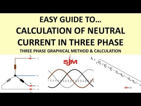
[0:10]This is easy guide to calculation of the neutral current in a three-phase circuit. Please like, share, and subscribe. So, let's have a look at a simple circuit. Here is a resistor with an ammeter connected to a 120-volt supply. And we can work out how much current would flow, and in this case, we apply Ohm's law and we would find out that 6 amps would flow. Remember, what flows out must flow back. So, the 6 amp goes out, 6 amps will come back in the neutral. And if we put an ammeter in both, it should read the same. If they don't read the same, it means you've got a fault that current is going somewhere else. So the neutral in a single phase installation, in this sense, it carries the return current. Hence, they are live conductors. Let's have a look at this circuit. This is a star-connected circuit. With a neutral connected to the star point. And if we have currents flowing in, what would flow back if anything along the neutral? So we're going to, first of all, we're going to look at a balanced load. What do we mean by that? It's the same amount of current in each phase. So we're going to take a value and we'll say 25 in L1, L2, and L3. So there's 25 amps in each phase flowing. And this is what the current wave forms would look like. They are three identical 25 amp. sine waves of current all peaking at different points in time, 120 degrees out of phase of each other because that's what three-phase actually is. And if we take a vertical line and put it straight line through any point along this particular set of sine waves and we were to add the values up at those given points where they cross, you'd have a positive and negative when you add them up it will equal zero. And if we add them at any particular point, the currents always equal zero at any point when we have this. Therefore, when we put an ammeter in a neutral conductor, in a balanced load as such, the current through the neutral will be zero. And if it's zero, guess what? We don't need it. It can disappear. So hence, in motors, for in three-phase motors, whether they're connected in star or delta, there is no neutral connection. Because they are balanced loads. And if they're not balanced load, they're called broken. So there must be a way of calculating these. And there is. There are many different ways how to calculate this. We're going to look at the graphical method. First of all, personally, I think it's one of the easiest. It wasn't the one I was taught originally, but it's one that is very good and easy for most people to understand. And it's we're going to pose it as a question, as always, determine the neutral current in the following load. The current in each phase, we're going to say 25, 25 and 25. We've already said on the previous one that it's going to be zero, but we're going to prove it. So, how do we go about doing this? Well, what we do, it's an extension of a phase diagram. But, effectively, it's a continuation of that drawing and we're going to pick a scale. And what we're going to try and draw is an equilateral triangle. And an equilateral triangle has an angle internal angles of 60 degrees. And it doesn't matter which phase you start with, but you're just trying to draw a triangle. As long as you remember each time you draw another phase, it is 60 degrees from the end of the last one. You'll get the idea, but you'll all know what triangles look like. And hopefully, you'll all know what an equilateral would look like. So, I'll draw L1, I'm going to draw 12 and a half centimeters. And these again are drawn to scale. And then we're going to put 60 degrees angle up there and draw the other one at 12 and a half centimeters at a 1 to 2 scale to give us our 25 amps. And then we draw the last one. L3 at 12 and a half cm. And what you'll notice is we physically do draw a triangle. And the reason this is the case is because each phase is equal, and therefore all the points meet. And therefore, because they all meet, there is no current flow in the neutral. You might think, well, that states the obvious, but you'll see when we have an unbalanced load, how that actually works and what I mean. So, let's move on to another question. So, they're going to look at the same one again, but this time, we'll give you different currents. And we'll say we have 25 amps, 10 amps and 7 amps.
[5:42]Again, it doesn't matter what phase you start off with. So pick one. Pick a scale, decide on your scale. Make sure it fits your paper that you're trying to do. And draw the line to scale. So we've got L1, 12 and a half centimeters again. In my scaling. And then 60 degrees up. I'm going to draw the other line current. And L2 is 5 centimeters, 1 to 2, so there's our 10 amps. And then from the other side, we're going to draw L3 and that one is 7 amps, so it's 3 and a half centimeters in length. Now you can see we are trying to make a triangle, it makes a bit more sense now, but it hasn't quite met. So how do we work out the neutral current for that? All we need to do now is draw a straight line from one point to the other. The length of this line, guess what? It represents the neutral current to scale. Of a 1 to 2 scale, so if we read off what the distance is, we get approximately 8.3 centimeters. And if we multiply 8.3 by 2, you get 16.6 amps. So therefore the neutral current in this particular circuit will equal 16.6 amps. Hopefully, you can see that's not too difficult. You can apply this to anything.
[7:21]On alternative method and actually one that a lot of students I find tend to prefer out of all the things that they come across, they prefer this one. And it is by far very accurate and it's by calculation. So we're going to have the neutral current in the following load. 25, 25 and 25. We already know the answer is going to be zero. But let's do it by calculation. And we've got a formula to remember. And because we love a formula, and here it is.
[8:00]And yes, this is the one that students tend to try to remember. And they do remember it often on the whole. So out of all the formulas they have, this is probably the biggest one, the longest one, and this is the one they remember. Yeah, sometimes Ohm's law, they get stuck on. But here we go then, so you've got IN is equal to the square root of the current in L1 squared plus L2 squared plus L3 squared. And then you minus the current in L1 minus L2 minus L1 times L3 minus L2 times L3. So that's effectively if you've thinking safe isolation, there you there your combinations that you tend to test between on just three phases. So, we're doing a combination of everything. And then once you've done all of that, you square root the whole answer. So, let's put the figures in. And it's 25, 25 and 25 all the way across. And if you put all of this into your calculator, you will get an IN of 0 amps. We already knew this, so if you get this as a question, you don't need to prove it. Or you do, maybe the question says prove by calculation and then just do the calculation or do the drawing. Either way, um if it doesn't ask for any of that and just says what's the neutral current, you know it should be zero. Now, we're going to look at the unbalanced load by calculation method. So here's our neutral current. What are we going to work it out to be? L1 is 25, L2 is 10, L3 is 7. Remember, we've already done a drawing for this, but we're going to do it by calculation. So let's use our very friendly formula. There's our values, and we need to put our figures into it. And if we do all this as a calculation, what we get is 16.7. That's accurate. And I think we got 16.6, I think on our drawing. So you can see how very close each method is. And to be honest, it's well within tolerance either way, but obviously on the drawing one, it does depend how well you do your drawing. So if you're not very good at doing drawings, you're not very accurate, then your answer, don't expect that to be very accurate either. Calculation, provide you put the numbers in and do it properly, then the answer will be very accurate indeed. So in summary, then, there's the graphical method, which is to draw a triangle. Calculation, which is that long formula. And a balanced load, neutral current will be zero. Other methods for calculation exist. There are plenty more out there that you could or could not use. And this assumes the power factor in each phase is the same. If it's not, they may not work. So ensure that is correct and enjoy. Sparky help, thank you very much.


